Test Electronics
Used - Reconditioned and Used Test Equipment
All Products
25mV to 1000V, 10µA to 0.5A 5Ω to 20MΩ antiquated
BK Dynascan 120 Laboratory Volt-Ohm-Milliammeter 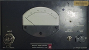
50Hz to 5MHz Sensitivity < 40 uV at 1 kHz antiquated
This 1212A unit null detector is a broadband balance indicator for ac bridge measurements from 50 Hz to 5 MHz. With the 1212-P3 RF Mixer and a local oscillator, its range can be extended to 60 MHz as a hetero dyne detector. The instrument consists of a three-stage, broadband amplifier. Germanium-diode clippers are used between stages to obtain the quasi-logarithmic response. The output meter has a linear scale. Earphone terminals provided. Sensitivity: Less than 40 uV at 1 kHz for 1% of full scale. Power Required: 1203-B (or 1203-B018) Unit Power Supply. Hum and Noise Level: Hum, 20 uV, broadband noise, 30 uV. Input Terminal: Locking CR874 coaxial connector. Accessories Supplied: Power-supply plug.Accessories Available: 1212-P1 and -P2 Filters, 1212-P3 RF Mixer. GR874 patch cords for input connection. 
4Hz to 750KHz Sine Wave Oscillator antiquated
4Hz to 750KHz sine wave oscillator. Old fashioned vacume tube technology. Very large front panel dial. Currently on a shelf in our reception room for show. 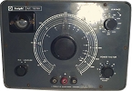
10pF up to 5000µF 0.5Ω up to 500MΩ antiquated
Resistance-Capacitance Bridge are most commonly used as a capacitor tester. The balanced bridge measures capacitance from 10pF up to 5000µF and resistance from 0.5Ω up to 500MΩ. During component value testing, the magic eye tube serves as the null-indicator. When the bridge is far from balanced, the target area of the magic eye tube glows completely closed green, and in fact overlaps. As the pointer dial approaches balance point, first the overlapping disappears and eventually the entire target area of the eye tube is completely open (dark). The bridge is balanced when the maximum dark area is indicated, and you can then read the value of your component on the faceplate scale. The magic eye tube is used for both Leakage testing and component value testing. 
25mV to 1000V, 10µA to 0.5A 5Ω to 20MΩ antiquated
260 Multimeter TECHNICAL DATA: DC Volts: Sensitivity: 20,000Ω per volt. Range: 0-1-2.5-10-50-250-500-1000V. DC Millivolts Sensitivity: 20,000Ω per volt. Ranges: 0-250mV AC Volts Sensitivity: 5,000Ω per volt. Range: 0-2.5-10-50-250-500-1000V. DC Current Ranges: 0-50 µA, 0-1-10mA, 0-100mA, 0-500mA. MV Drop Approx.: 250mV, 250mV, 280mV, 400mV. Range: 0-10A mV Drop Approx: 250mV. Resistance Ranges: R x 1 0-200Ω 12 ohms Center. R x 100 0-200,000Ω 1,200Ω Center. R x 10,000 0-20MΩ 120,000Ω Center. Accuracy DC Voltage Ranges: 2% of Full Scale. AC Voltage Ranges: 3% of Full Scale. 0-50µA Current Range: 1.5% of Full Scale. 0-1mA to 10A Ranges: 2% of Full Scale. Resistance Ranges: R x 1 (0-2000 O) 2.5° of Arc R x 100 (0-200,000O) 2° of Arc. R x 10,000 (0-20MΩ) 2° of Arc. Accuracies specified are for the 260-SP in a horizontal position. *Responds to the average value of an AC current and is calibrated to indicate the rms value of a pure sine wave.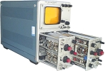
10 MHz 10mV/div to 10V/div in 10 Steps antiquated
The 3A6 Amplifier is a general-purpose, dual-trace plug-in unit designed for use in the Types 561B, 564B and 565 Oscilloscopes. The Type 3A6 features two separate channels with identical characteristics. It can be operated in any one of five modes for a variety of single and dual-trace displays. Two Type 3A6's can be used for X-Y curve tracing, but without synchronized switching or channel pairing. BANDWIDTH DC to 10Hz at 3dB down. AC-coupled low-frequency response is 2Hz, 0.2Hz with 10X probe. RISETIME Approximately 35ns. DEFLECTION FACTOR 10mV/div to 10V/div in 10 calibrated steps, 1-2-5 sequence; accurate within 3%. Uncalibrated, continuously variable between steps and to approximately 25V/div. INPUT RC 1 megohm paralleled by approximately 47 pf. MAXIMUM INPUT VOLTAGE 600V combined DC + peak AC. OPERATING MODES Channel 1 only (polarity of Channel 1 can be changed to provide 180° inversion); Channel 2 only; Alternate -- Channel 1 and 2 switched electronically on alternate sweeps; Chopped -- successive 4µs (approx) segments of each channel are displayed at an approx. 135KHz rate per channel (chopped transient blanking is provided); Added -- outputs of CHannel 1 and 2 added algebraically. INTERNAL TRIGGER SIGNAL Selectable from the output of Channel 1 only or from the combined output of the unit. Triggering from Channel 1 only permits viewing the true relationship between two signals when operating the unit in either alternate or chopped mode.
10 MHz .5us/div to 1s / div in 20 Steps antiquated
The 3B3 - Time Base Delayed and normal triggering to 10 Mhz. Single sweep operation. Time Base .5us/div to 1s / div in 20 steps. X5 Magnifier. Delay Time .5us/div to 1s / div in 1-2-5 sequence. The Type 3B3 Time Base Unit is a plug-in time base generator designed for use with the Tektronix Types 561A, 561B, RM561A, 564, 567, and RM567 Oscilloscopes. The Type 3B3 provides normal or delayed sweeps at 20 calibrated rates from 0.5 microseconds per division to 1 second per division. In delayed sweep operation, the Type 3B3 gives continuous calibrated sweep delay from 0.5 microsecond to 10 seconds after receipt of a triggering impulse. SWEEP RATES Both normal and delayed sweep rates from 0.5 microsecond per division to 1 second per division in 20 calibrated steps. A variable control provides uncalibrated sweep rates between steps and also extends the slower rate to approximately 2.5 seconds per division. Calibrated sweep rates for both normal and delayed sweeps are typically within 1%, and in all cases within 3% of the TIME/DIV. and DELAY TIME RANGE switch settings. SWEEP MAGNIFICATION The display can be magnified 5 times, extending both the normal and delayed sweep rates to 0.1 microsecond per division. Sweep rate accuracy with the 5X magnificiation remains within 5% of the TIME/DIV. and DELAY TIME RANGE switch settings. SWEEP DELAY The calibrated sweep delay is continuously variable from 0.5 microsecond to 10 seconds. Delay accuracy is 1% of full scale reading, and delay time linearity is within 0.2% of full scale from 5 microseconds to 2 seconds of delay. Time jitter is less than 1 part in 20,000 of the maximum available delay interval. SINGLE SWEEP All modes of operation can be displayed as a single sweep for photographic recording.
10 MHz Solid State Design antiquated
The 561B incorporates the revolutionary new CRT rectangular faceplate allowing a more compact CRT. Mechanically precise ceramic envelop and phosphor side printed face plate graticule markings eliminating parallax errors and allows for better edge illumination. Supports all 2 and 3 series plug-ins. New 3 series plug-ins achieve a higher 10MHz system bandwidth.
1V to 5KV, 10µA to 10A 5Ω to 100MΩ antiquated
(description below copied directly from manual July 1959) ACCURACY Your 630-PL is accurate to within 3% of full scale reading on all DC ranges except the 5000 volt range which is within 5%, 4% on all AC ranges except 5000 volts which is 5%, and 3% of the scale length on all resistance ranges. Precision, non-aging resistors insure lasting accuracy. All units are calibrated at 77°F. AC ranges are calibrated on a 60 cycle sine wave. In choosing ranges always endeavor to have the readings fall in the upper (or right hand) half of the scale for greatest accuracy. RANGES The following ranges are self contained in your 630-PL: DC Volts 2.5-10-50-250-1000-5000 at 20,000 Ohms per Volt. AC Volts 0-3-10-50-250-1000-5000 at 5,000 Ohms per Volt. DC Microaxnperes 0-100 at 250 Mv. DC Milliamperes 0-10-100-1000 ot 250 Mv. DC Amperes 0-10 at 250 Mv. Ohms 0-1000-10,000 (4.4-44 at center scale). Megohms 0-1-100. . (4400-440,000 at center scale). Output Volts(AC) 0-3-10-50-250-1000 at 5,000 Ohms per Volt. Decibels -20 to +11, 21, 35, 49, 61, 75 on 600 Ohm line. Your 630-PL is well constructed but like any instrument should be handled carefully. You will also want to keep the panel clean as cleanliness and carefulness go hand in hand.


